I Made an Absolute Unit of a Sideboard

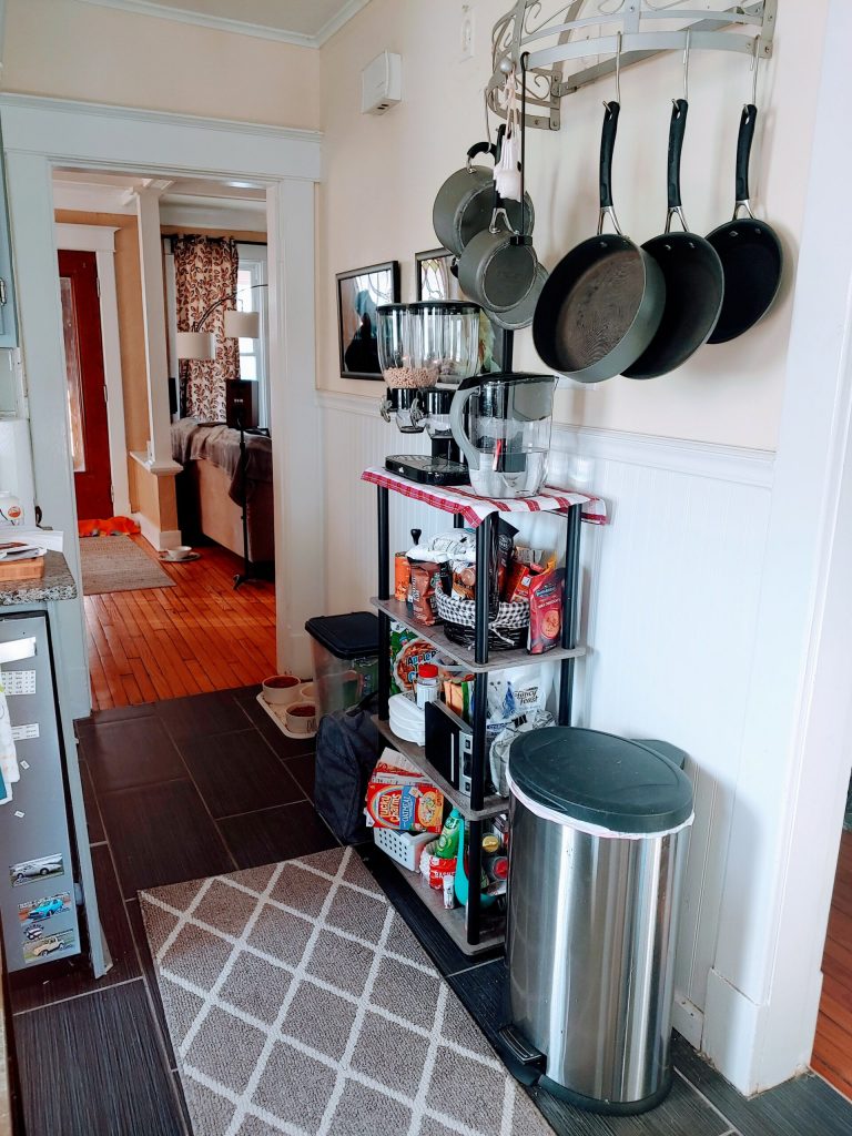
Here’s a picture of my kitchen a few days ago:

That rickety plastic shelf is holding a lot of stuff up; it looks kind of unkempt and it’s pretty wobbly, especially when there’s something heavy on top of it. Not pictured is our pantry cabinet that’s almost overflowing with stuff and the kitchen cart packed to the gills. It’s hard to find things easily in both locations. Notice the huge amount of empty space to the left of the shelf, above the cat food bowls. I devised a plan to take advantage of this area and add a ton of new storage space to the kitchen.

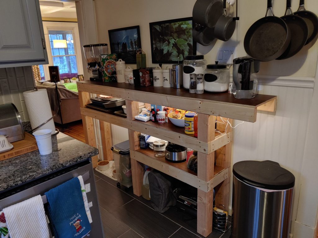
Here’s the result:

I put LED strip lights on the underside of two of the shelves. It makes a huge difference.

The old plastic shelf was moved to the dining room and in its place is a shelf/sideboard unit that I made myself. It’s made with 2×4 and 4×4 lumber, so it’s pretty chonky, but it’ll never collapse. The shelf surfaces are covered with peel-and-stick vinyl flooring, which was an incredible pain to cut, but it looks and feels great. The effect of the extra storage capacity cannot be overstated. The pantry cabinet and kitchen cart are now uncluttered and much more usable. The overall look of this thing could be charitably described as “rustic,” so I got some dark stain that I’ll be applying as soon as the driveway is dry-ish for a day. I’ll also be adding a paper towel holder above the trashcan and a bar with S-hooks for oven mitts. I’m really pleased with the results, and I think it’ll be even better when it’s totally finished.

A Flurry of Lego Activity

Over the past couple weeks, I got around to assembling a few Lego sets I’ve had around the house for quite a while.

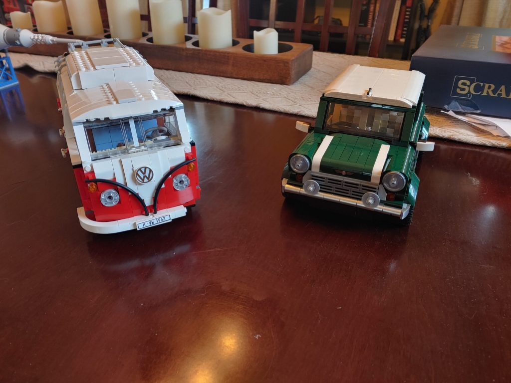
First up was the Mini, set number 10242. This was a really enjoyable build, with some super cute details like a picnic basket complete with tiny bread and cheese. Like the reviewer above, I think the steering wheel is kind of too big for the rest of the car, but overall, it’s a great set.

Next up, I repaired the VW Bus, set number 10220. This set was a birthday present from my wife, then girlfriend, three years ago. I put it together on my birthday weekend, and set it on the sideboard in the dining room for the night. I woke up to discover our three-month-old kittens knocked it over during the night, shattering it all over the floor. I gathered up all the pieces and put them in a box, which sat on a shelf in my office until about a week ago when I decided to put it back together. I took apart almost everything that was still together and built it back up. When I finished, I discovered I was missing a piece. Luckily it wasn’t a set-specific piece and I ordered a few on eBay. This is a great set, with a ton of fun little details inside the van. Totally worth whatever the asking price is these days.

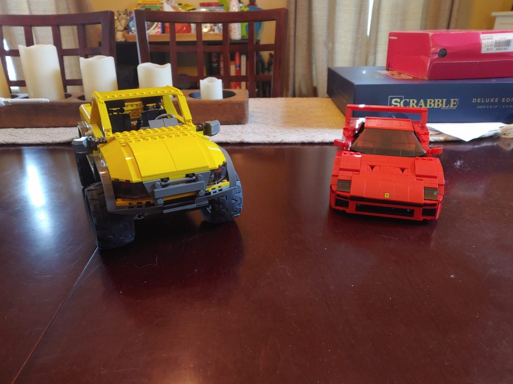
Most recently, I put together the Ferrari F40, set number 10248. My wife’s parents got this for me as a Christmas or birthday present a few years ago. Like pretty much all the Creator Expert sets, this one was a fun build. I was especially impressed with how the set created the angled section of the car behind the doors. The actual F40 is pretty angular, so it lends itself well to a Lego set I think.

The yellow truck is set number 4404, also known as Land Busters. I’ve had this set assembled for a while, but brought it to my house from my parent’s recently. This set came out in 2003, but I’m not sure when it was retired. I got it when I was a kid and I remember my mom being annoyed that my dad bought it for me. At close to 800 pieces, it was beyond my ability as an eight year old. I finally got around to finishing it like 10 years later. It’s apparently considered a decent, but maybe underwhelming set, mainly due to a non-functional steering wheel.

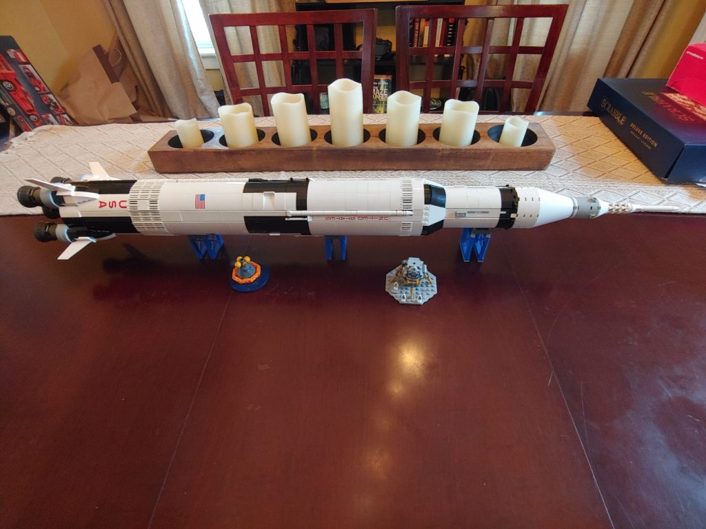
I finally got around to using a Lego gift card my parents got me last year. I a month or so ago that Lego was re-releasing the Apollo Saturn V, identical to the original set, but with a new set number. I regretted not getting this during the original run, especially after I saw the completed set at my uncle’s house. To say it’s enormous is an understatement. It looks just like the real thing, and the building techniques are very interesting. 10/10, absolutely worth the price.

During this storm of Lego, I’ve learned that retired sets are often worth multiples of their original price, even in used condition. It makes me feel a bit more at ease about buying Lego sets, because there isn’t really such a thing as a cheap Lego set. Not that I ever plan to sell any, knowing they increase in value over time makes me feel a little better.

Since my last post, the world has kind of come to a screeching halt. I’ve decided to take a little break from getting my new business going, for a few weeks at least, to see how things go. I’ve had some more free time on my hands lately.

I fired up the 3D printer the other day to try to get it dialed in a bit better. It occurred to me that I’ve never printed a Benchy before, so I gave that a shot. With the exception of oozing on the corners of the stern, most of them came out in pretty good shape. One change I made early on that seemed more helpful than I expected was to change out the computer running the show. I had my printer connected to a Raspberry Pi Zero W running OctoPi. I discovered a couple months ago that the Zero W is not recommended for use with OctoPi, but didn’t give it much thought. I switched out the Zero W for a Model 3B+ I had hanging out and it seemed to make some of difference. At the very least, the printer responds to commands from OctoPrint like moving the print bed much faster. I printed a couple new cases for my various Raspberry Pis yesterday.

I came back to the printer this morning to find it no long functional. I think there’s an issue with the power supply. The fan inside doesn’t spin. The display on the front of the printer says there’s a problem with either the X or Y axis limit switches. I opened up the printer hoping there was just a loose connection, but I tried all of them to no avail. I gave the power supply a few smacks with a hammer, but that didn’t help either. I looked for new power supplies and found a few for around $60. I’m not totally sure it’s the power supply, so getting a new one would be a $60 shot in the dark for a mediocre 3D printer. So it looks like I’m in the market for a new 3D printer.

It feels like everyone on the 3D printing subreddit recommends the Creality Ender 3/Ender 3 Pro for people with a budget under $500. The Ender 3 is a fine printer, and pretty cheap. Almost criminally cheap, actually. The Ender 3 Pro is only $240 right now, making it really, really easy to get into 3D printing. For that price, I can’t believe there isn’t one in every house. There are a few things about the Ender 3 I don’t like though. Number one, it looks like shit. It looks like something that was slapped together in a garage, with the exposed power supply being its most egregious fault.

Ender 3 Pro

I suppose I could get over inferior aesthetics for superior functionality. The functionality equation breaks down for me due to the way the axes move. The extruder moves though the X and Z axes, while the print bed moves though the Y axis. This means that every time a Y axis movement needs to happen, which is all the time, your object gets jostled around. On objects with a short height, this might not be a problem, but as things get taller they’re more likely to wobble and cause problems with the print quality.

Creality also sells the Ender 5 Pro, which is what I think I’m going to buy.

Ender 5 Pro

The Ender 5 Pro offers a slightly larger build area than the Ender 3, with a print bed that moves in the Z axis only. The price is fairly attractive at $390. Allegedly, it should be pretty quiet too. It still has that rustic, garage-made look, but it’s not too awful. It comes as a kit that requires about a half hour of assembly according to reviews. Like all Creality and Prusa printers, there is a huge community behind them providing printable parts to improve or repair the printers and support for dialing in the printer or installing modifications or troubleshooting. I posted on Reddit to see if anyone has any opinion to offer on this printer. If I don’t hear anything negative I’ll probably order one in a few weeks.

Yesterday afternoon I had such a “duh” moment. I realized that I can use a Megasquirt system on the Saab engine I was originally planning on using. So now the plan is to get myself a 2004-2011 Saab 9-3 2.0T with the B207R engine. 2003 and 2008-11 all wheel drive models had secondary air injection which is stupid. I can remove it, but it’s just easier to not have it in the first place. Hopefully, I’ll be able to use the car’s original computer to run things, but if that’s not possible I can always go with Megasquirt. This engine would be easier to run with Megasquirt than the LE5 anyways because the B207 doesn’t have variable valve timing.

Engine Height Troubles

I took a look at the LTG engine dimensions on the GM crate engine site earlier today. At about 27.3 inches tall according to GM, the LTG is probably too tall to use in a Locost, at least easily. The Locost forums say that the Miata 1.8 liter engine, a popular choice, is fairly tall at around 23 inches and requires the oil pan to sit below the frame rails. Clearly then, the LTG is too tall. Turns out it’s tricky to find dimensions (overall length, width, height) on most engines, unless they’re offered as a crate engine or are very popular in standalone applications, so I’m not totally if an LHU or LNF would fit either. I’m not totally sure if any Ecotec engine would fit, but I think I’ve found a decent option.

Obviously, buying a whole car to extract the engine, accessories and wiring from would be ideal, but I’m not sure it’s going to be possible for a low enough amount of money. The cars containing the LNF and LHU engines are still fairly new, and in the case of the LNF, rare. It’s pretty unlikely I’m going to find a rusted out 2013 Buick Regal Turbo. So a more common and older engine would be easier to work with.

I think I’ll be setting my sights on an LE5, a 2.4 liter naturally aspirated four cylinder found in a bunch of shitty, uninspiring GM cars from 2006 to 2012. In the form I’m most likely to find, it puts out 169 horsepower and 162 ft-lbs of torque. That should be totally fine for a 1500 or 1600 pound car, even though it’s not the 260 horsepower of the turbo engines. I think I’d probably run the engine with a Megasquirt 3 system, which should be able to deal with the engine’s variable valve timing and avoid the headache of using the GM ECU without the rest of the car. The Megasquirt is also infinitely tuneable, so with some effort I might be able to eke out a little more power. And if I want a lot more power, the turbo from the Saab 9-3 bolts on with some effort. I’m looking into grafting on the individual throttle bodies from a motorcycle for this engine. I might even be able to

So that’s where the project stands for now. Today and tomorrow are going to be pretty warm, and hopefully it stays that way. I need to get the garage in ship shape before I start building anything.

Locost Concept Update

The Suspension

Last week we got a Saturn Sky in at my work. Since they came out, I’ve always thought they were a great looking car, maybe even a work of art. The interior, it turns out, leaves a lot to be desired. It’s everything terrible about GM from 10-15 years ago, but I suppose it was a pretty inexpensive car when it was new.

2009 Saturn Sky Redline Ruby Red Limited Edition.jpg
By ReedredOwn work, CC BY-SA 3.0, Link

The Sky/Solstice was built on the GM Kappa platform, a brand new design for a two seat convertible similar to a Miata. Knowing this, I was interested to inspect the suspension design on this car. The Miata, at least the NA and NB generations I’ve looked into, have simple front and rear spindles that are easy to adapt the the Locost design. It turns out the Sky might be even better.

The front and rear spindles appear very similar (I suspect they may even be identical). They’re made of aluminum, which is appealing due to its lighter weight than the Miata’s iron spindles. Both front and rear take ball joints top and bottom, with a tie rod in the middle. This is the same as the Miata in the front, but different in the back. The Miata does not use ball joints in the back, just a simple clevis. The ball joints and tie rod on the Sky allow the toe to be adjustable in addition to camber. The only thing I don’t really care for is that the wheel speed sensor is integrated in the wheel hub/bearing assembly. They’re a lot more expensive than a press in bearing and I’m not sure yet if I can make use of the sensor.

They didn’t make a ton of Solstices and Skies, so finding a reasonably priced parts car a reasonable distance from me would be tricky. Luckily the parts I need are available for an okay price on eBay. On a whim, I cruised around and ended up with a set of four brake calipers with bolts and hoses, and both rear spindles. The calipers were $120, and the spindles $112. I think those are pretty tough prices to beat. If I decide not to build the car, I can always clean up the parts and sell them for a bit more than I paid.

The Drivetrain

My original plan was to use the B207R/Lk9 out of a Saab 9-3 2.0T. They’re very easy to find for cheap in my area. I’m also a Saab mechanic, so I can get any parts I need to refresh the engine and I have easy access to parts and electrical diagrams. I’ve decided not to use this engine though. While it’s a GM engine, there are a few proprietary Saab parts, the ECU among them. At work, we replace ECUs on 9-3s very frequently. The “new” ones aren’t new anymore, they’re rebuilt and have a high failure rate. The parts company has introduced another ECU part number, but using it requires modification to the wiring harness, and I suspect it won’t be any more reliable than what we already have.

With that in mind, I decided to look for new engine options. If money was no object, I’d probably go for an aluminum block GM V8. But money is an object, so I’ll have to go for something less expensive. I think a four cylinder of 2 liters or less is more in the spirit of the Lotus 7 anyways. I took a look at GM’s current crate engine offerings. Their four cylinder option, the LTG, looks like just the ticket. Of course a new engine would be way too expensive, but the LTG is available in several production cars in both front and rear wheel drive configurations (I’m not sure what the difference is and whether it’s important to me though). It puts out up to 272 horsepower and 295 ft-lbs of torque, depending on the car. The LTG can be found without too much trouble in the Cadillac ATS, Buick Regal and Chevrolet Malibu. It seems to be fairly inexpensive to get a wrecked Regal, so I’ll probably try to take that route. The LHU, as installed in the Regal GS or Buick Verano Turbo, would be a fine alternative to the LTG. The LNF, in the Solstice GXP and Sky Red Line would also get the job done, but would probably be tougher to track down.

Any of those engine options should mate easily with the AR5 transmission I’ve been planning on using. I’m not totally sure about options for a flywheel and clutch, but it shouldn’t be terribly difficult to figure out. I hope.

With all this GM stuff, it makes sense to use a GM differential. My ideal choice would be the 3.73 limited slip unit out of a Sky Red Line or Solstice GXP. Those seem a tad expensive for me, so another option could be the 3.42 limited slip differential from a Cadillac CTS. I’ve read they’re the same basic thing, but I’m unsure if the Solstice/Sky axles would fit right into the CTS differential. I’m also concerned about having to have the axles shortened or lengthened because I suspect (but don’t know) that it might be expensive.

So that’s where the concept for this project is at the moment. I’m still not totally sure if it’s going to happen, mostly because my garage needs to get into decent shape before I build anything. The majority of the work shouldn’t be very expensive, but getting someone to add a few electrical circuits to the house might be. I’ll have to call some places and get estimates. After that’s done, the holes in the siding need to be fixed, new overhead doors need to be installed and lighting and electrical outlets need to be added, all of which I can probably handle myself. We’ll have to see how it goes.
I’ve made a small change in my exposure meter design. Rather than using one set of buttons to increase or decrease the shutter speed or aperture, I’m going to use one rotary encoder for each. I realized, as I was going to make a menu system for changing the ISO, shutter speed or aperture mode and perhaps one or two other items, that I really had no idea what I was doing. I found a few different menu setups for Arduino on forums and other places, but I didn’t really understand them because I don’t have enough experience. I thought it would be better to not use elements I don’t have a firm grasp on.

So instead, I’m going to use one rotary encoder each for changing the ISO, shutter speed and aperture. The encoders also have a built-in button, so I might use that to trigger the reading of the light sensor. I might also use a separate button for that. I haven’t decided yet. Either way, having a separate device to manipulate each variable should make the coding simpler.

Update on the exposure meter

The parts for the exposure meter came in last week. It seems that everything works just fine, except for the breadboard I picked out of the pack of 3 I ordered. It seems like the lower half of it does not work. Hopefully the other two are better.

Anyways, these are the major parts in the system:

  • Adafruit Mini Metro. This is an Arduino-compatible, ATmega328-based microcontroller. It’s the brain that processes the input from buttons and the light sensor and displays everything on the display.
  • 128×64 OLED display. This seemed like a good choice for this project because the OLED displays are easy to read in bright light, and I’ll be using this thing outside most of the time.
  • TSL2591 light sensor. This senses the light and gives the microcontroller somewhere to start when deciding what shutter speed or aperture to suggest.

So far, I have a set up that does the following:

  • Reads the light sensor and returns a value in lux.
  • Plugs the lux reading into an equation to get an exposure value.
  • Plugs that exposure value into one of two equations:
    • One equation finds a shutter speed that works with a selected aperture.
    • The other equation finds an aperture that works with a selected shutter speed.
  • Sends the lux reading, exposure value, selected ISO, and the computed shutter speed or aperture to the display.

Now I need to create a menu system for adjusting a few settings, such as the ISO, changing the mode from shutter speed to aperture and perhaps setting a minimum shutter speed or aperture value. I also need to come up with a way for the results from these equations to get rounded to the nearest third of a stop so they’re easier to use. That might be the trickiest part, but I guess I’ll come up with something.

Parts are on the way

I placed the order for all the parts I should need to create my exposure meter. Most of the parts are coming from Adafruit, and most of the supplies are coming from Amazon. The total bill was around $170, but I had to buy some supplies and tools that will be available for use on future projects.

The main parts in this build are an Adafruit Mini Metro, TSL2591 light sensor and a monochrome OLED display. The Mini Metro is an Arduino-compatible microcontroller. It’ll take inputs from buttons and the light sensor, interpret them, and then show the results on the display. The light sensor will give me my light reading in lux, which I can then plug into a formula to solve for either the correct aperture or shutter speed. The OLED display should be pretty easy to read in a bright area. Plus I’ve wanted to use one in a project for a while. Other parts coming aboard are three buttons, an on/off button and some 9 volt battery connectors.

I had to buy some supplies for this, because it’s been quite a while since I’ve build something. I needed more hook-up wire, jumper wires, and breadboards. I also got some jumper wire pins, wire housings and special crimpers to put them together so I’ll end up with a more elegant package of wires at the end.

The Amazon stuff should be in on Monday they say. The Adafruit things don’t have an estimate, but I’d imagine they’d be in by Wednesday because they’re only traveling from New York City. Hopefully next weekend I’ll have a working prototype done on the breadboard.

I’m going to build a thing!

I currently have in my possession four cameras of different types (five, I suppose, if you count my mildly broken Canon AE-1), one of which is a Rolleicord. For those of you who don’t know, a Rolleicord is a TLR, or twin-lens reflex, camera, which means it has two lenses. The top lens provides the image for the viewfinder, and the bottom lens exposes the film. This was a common setup until the 1970’s when SLR (single-lens reflex) cameras became cheaper.

I bought it because it was probably the least expensive way to get started with medium format photography. As you can see, the 6x6cm image created by this camera is significantly larger than the 35mm that most people would consider normal, and it’s enormous compared to the APS-C size image sensors in many digital cameras.

I really like this camera, mainly because of the images that come out of it. The pictures have a quasi 3D feel to them that 35mm film and digital just don’t. It’s fairly easy to take candid pictures with this camera thanks to the top mounted viewfinder and extremely quiet leaf-style shutter. Since you have to look down into the viewfinder, most people don’t realize you’re taking a picture.

The main issue with the camera is that the picture-taking process can be slow, especially if the lighting conditions are changing. There is no built-in exposure meter, so you have to supply your own. I’ve been using an app on my phone since I got the camera, with totally fine results. The app imitates an old-school analog meter though, so the result it displays is kind of “fuzzy.” It gets the job done, but a real exposure meter would really add some convenience.

I have a car show coming up on the long weekend, so I thought I might order a cheap one on Amazon and give it a shot. Turns out, there really aren’t any cheap exposure meters out there. I was hoping for something around $50, and I’d even take a used one, but there doesn’t seem to be anything in that price range.

It finally hit me today that I could probably make my own exposure meter with more features for less money than I could buy one. I really love making things rather than just buying them if I can, even if it doesn’t save much money.

For this project, which has been done a couple times before according to the internet, I’ll use an Arduino to read a TSL2591 light sensor and show the results on a small OLED display (I’ve wanted to use an OLED display for ages). I’m not totally sure yet how I’m going to change settings on this machine, but I’ll come up with something. I’ll draw up a case for it in SolidWorks and then 3D print it.

I’m pretty excited about this, because it’s been a while since I’ve built a thing. I’ll try my best to post some updates, but there will definitely be one when the whole thing is finished.